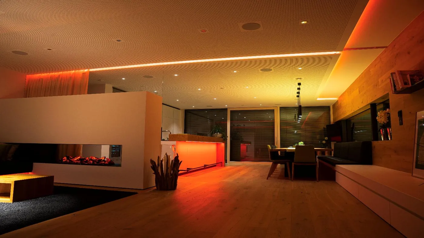
HVAC control
HVAC Control Strategy: A Practical Guide
How HVAC control strategies are structured, from chiller plant and air handling to fan coils and underfloor heating, and how to make comfort and plant performance measurable.
Quick answer
HVAC control strategy is the set of sequences that decide when plant runs, how much capacity is delivered and how zones are held at setpoint. Good strategy coordinates chillers, pumps, air handling units, fan coils and terminal heating, then proves the result with trends rather than assumptions.
The control chain, from sensor to sequence
Every HVAC strategy is built from the same chain: a sensor measures a controlled variable, a controller compares it with a setpoint, and an actuator changes the output. The engineering lies in what happens between those steps. A proportional-integral loop needs a sensible deadband, a realistic output range and a fallback state when the sensor fails. A staging sequence needs thresholds, minimum run times and rotation. A schedule needs an occupancy model and an override policy. When these are written down, a strategy can be reviewed, tested and tuned. When they exist only as a technician's habit, the building cannot be commissioned consistently, and a change of staff quietly changes the building's behaviour. The sequence should also state what the system does at the edges: sensor fault, network loss, actuator failure and the first hour after a power cut. A strategy also needs a defined priority: safety first, then plant protection, then comfort, then energy. Without that order, two legitimate objectives will fight each other every afternoon. The written sequence is the design; the programme is only one implementation of it. It should name the sensor that owns each loop, so a failed device cannot be replaced by a value from somewhere else without a decision.
- Controlled variable, setpoint and deadband
- Output range, limits and fail-safe position
- Schedule, occupancy and override policy
- Alarm and fallback behaviour
Chiller plant strategy
The chiller plant is where a large share of HVAC energy is decided, so it deserves a sequence rather than a fixed setpoint. A common approach is to reset chilled water supply temperature upward as valve positions fall, within limits set by the most demanding zone. Chillers are staged by load and runtime, with rotation to equalise hours and protection against short cycling. Pumps follow differential pressure or flow, with the sensor placed where it represents the real load. Condenser water optimisation coordinates tower fans, bypass and approach temperature. The sequence must also handle minimum load, chiller lockout, fault recovery and manual override. None of these strategies is universal; each depends on plant configuration, controls capability and the way the building is used. Metering and trend data are part of the strategy, because staging decisions without feedback are guesswork. A plant sequence that looks elegant on paper is only useful if the valves and sensors have the authority to execute it. The sequence should also define how the plant behaves during a changeover, because that is when most alarms are generated. Lead-lag rotation should follow runtime and starts, not a fixed weekly swap that ignores actual use. A plant sequence should also state which measurements it trusts when two sensors disagree.
- Chilled water reset within zone limits
- Load-based staging with runtime rotation
- Variable pump control with a representative sensor
- Condenser water and cooling tower optimisation
Air-side strategy
Air-side control shapes both comfort and ventilation. Supply air temperature is often reset according to zone demand rather than held at a fixed value. An economiser brings in outdoor air when conditions allow, with dampers and fans coordinated to avoid pressure swings. Demand-controlled ventilation uses CO2 or occupancy to modulate fresh air between a minimum and a maximum, with a deadband and a fault response. Variable air volume systems benefit from static pressure reset, which lowers fan energy until the most demanding box is nearly open. Night purge can remove heat using cooler outdoor air, subject to security, humidity and noise limits. Frost protection, filter alarms and fan fault detection belong in the same sequence, because a ventilation strategy that ignores them will fail in winter or go unnoticed in summer. Where the building has operable windows or natural ventilation, the sequence must define how mechanical and natural modes interact. The air-side sequence should also state how it interacts with fire modes and smoke control, which always take precedence. A damper schedule that is never tested is an assumption, not a control strategy. The economiser changeover should use an enthalpy or dry-bulb comparison, not a fixed outdoor temperature that suits one season. Ventilation zones should follow the air distribution, not the floor plan.
- Supply air reset by zone demand
- Economiser with coordinated dampers
- CO2-based ventilation with min and max limits
- Static pressure reset for VAV
- Night purge with safety limits
Terminal and hydronic strategy
Terminal control is where occupants experience the system. Fan coil units need valve control, fan speed selection and an occupancy setback that respects local overrides. Two-pipe systems need a changeover strategy; four-pipe systems need a deadband that prevents simultaneous heating and cooling. Variable air volume boxes need airflow limits, reheat control and a response to duct pressure. Underfloor heating behaves differently: the slab stores heat, so the flow temperature is usually weather-compensated and limited, and the control loop must anticipate rather than react. Fast setpoint changes in a heavy slab waste energy and cause comfort overshoot. Radiators and trench heaters have their own valve authority and response times. A single room schedule copied across all terminal types is a common source of complaints. The design should state which terminal owns the room temperature and which one is allowed to trim it. Commissioning should include a slow-response test, because a slab that reaches setpoint in ten minutes is probably not being controlled correctly. Where a room has both heating and cooling, the deadband should be wide enough to prevent them running together, and the sequence should log any simultaneous demand for review. A terminal that cannot meet its airflow at design conditions should be reported, not compensated by a higher fan speed.
- FCU: valve, fan speed and occupancy setback
- VAV: airflow limits, reheat and duct pressure response
- Underfloor: weather compensation and slab limits
- Changeover and deadband for two-pipe systems
Planning ranges and setpoint bands
Planning ranges help a design review, provided they are labelled typical and replaced by project data. Chilled water supply commonly sits between 6 and 9 degrees Celsius, with a design delta-T of 4 to 6 kelvin; a low delta-T is a symptom, not a setpoint. Supply air might be reset between 12 and 16 degrees Celsius depending on the terminal type. Occupied room temperature is often held at 22 to 24 degrees Celsius with a deadband of 1 to 2 kelvin, while unoccupied setback might be 2 to 4 kelvin away from the occupied value. Duct static pressure might be reset from a design value down to 30 or 40 percent of it, subject to terminal minimums. Fan coil fan speeds are often three-stage or modulating. These figures are planning aids. Local codes, the design brief and the equipment data govern. The important discipline is to record the design intent and the acceptable band next to each setpoint, so that a later adjustment can be judged against something other than personal preference. A setpoint without a documented band becomes a negotiation every time the building feels slightly warm. The bands should be reviewed when the tenant fit-out changes, because a new layout can invalidate the original zoning.
- Typical water, air and room temperature bands
- Deadbands and setback ranges stated explicitly
- Design intent recorded beside every setpoint
- Local code and equipment data override the range
Control modes compared
Control modes are often discussed as a hierarchy, but they answer different questions. Two-position control suits equipment that cannot modulate and needs a minimum run time. Floating control suits actuators without position feedback and needs a defined travel time. Proportional control is simple but leaves an offset; proportional-integral removes the offset at the cost of tuning. Staging sequences coordinate discrete machines; reset schedules shift a setpoint from a design value; adaptive strategies learn from trend data over weeks. None is inherently better. The choice depends on the actuator, the sensor, the process time constant and the tolerance the space can accept. A slow process such as a slab or a large chilled water loop should not be driven by a fast room loop. A fast process such as a VAV box should not be tuned with a ten-minute averaging window. The design should state the mode, the tuning constants and the expected response time for each controlled variable, because those three together are what commissioning actually verifies. A mode chosen by habit is the most common reason two identical rooms behave differently. A control mode is a commitment to a response shape, and that shape should be visible in the trend.
- Two-position for on-off equipment with minimum run times
- Floating for actuators without position feedback
- PI for modulating valves, dampers and fans
- Staging and reset for plant-level coordination
Common design mistakes
Most HVAC control problems are design problems that appear later as complaints. Oversized valves lose authority and hunt at low load. Minimum fan speeds are set high to avoid alarms, so the system never reaches part-load efficiency. Resets are installed but left disabled because nobody agreed the limits. Sensors sit in dead zones, near diffusers or in direct sun. Schedules are overridden during fit-out and never restored. Sequences are documented in a subcontractor's file that nobody receives at handover. Each mistake is cheap to prevent at design stage and expensive to discover in operation. A design review should walk through every sequence, confirm the sensor and actuator assumptions, and ask what the system does when a signal is missing. The review should also check that the sequence can be tested without disabling safety functions or disturbing occupants. Finally, the review should confirm that the documented sequence matches the programmed sequence, including every override. The most common finding is not a missing control but a control that nobody can explain, which is why the written sequence matters as much as the programme. A design review that cannot name the person responsible for each sequence is not finished.
- Check valve and damper authority
- Agree reset limits in writing
- Verify sensor location and calibration
- Restore schedules after fit-out
- Include sequences in handover documents
Commissioning checks and seasonal review
Commissioning should prove the strategy at part load, not only at design load. Each loop is stepped and its response recorded; each staging sequence is forced through its thresholds; each reset is driven from one end of its range to the other. Sensor readings are compared with a calibrated reference at at least two points. Valve and damper strokes are observed, not assumed from the command. Alarms are induced and cleared. The results are recorded against the sequence, with the date, the conditions and the person who performed the test. Seasonal review is normal: a sequence tuned in summer may need different limits in winter, and a chiller plant that behaved well at 30 percent load may short-cycle at 10 percent. The review should compare trend data with the commissioning record, adjust only what the data justifies, and record the change. A building that cannot show a week of normal operation with the sequence enabled has not finished commissioning, whatever the sign-off sheet says. The review should also check that the alarms generated during the season are the ones the design intended, not a new population created by a changed schedule. Seasonal review should be scheduled before the season changes, not after the complaints arrive.
- Step each loop and record the response
- Drive resets across their full range
- Compare sensors with a calibrated reference
- Review trends against the commissioning record
HVAC control strategies, failure modes and checks
16 rows| Strategy | Controlled variable | Typical sequence | Common failure | Commissioning check |
|---|---|---|---|---|
| Chilled water reset | Supply water temperature | Reset upward as valve positions fall | Reset disabled or over-aggressive | Drive the reset across its full range |
| Chiller staging | Online chiller count | Stage by load and runtime, rotate lead | Short cycling at part load | Force stages at low load and log starts |
| Primary pump control | Differential pressure | Variable speed with a remote DP sensor | Sensor at the wrong end of the loop | Compare DP at the sensor and the far end |
| Condenser water | Approach temperature | Optimise tower fans and bypass | Tower fans held at fixed speed | Vary load and observe approach recovery |
| AHU supply air reset | Supply air temperature | Reset by zone demand | Fixed setpoint all year | Step zone demand and track supply air |
| Economiser | Damper position | Free cooling when outdoor air allows | Damper stuck or badly interlocked | Stroke dampers and verify changeover |
| Demand-controlled ventilation | CO2 and occupancy | Modulate fresh air and fans | CO2 sensor only in the return duct | Inject CO2 and observe staged response |
| VAV static pressure reset | Duct static pressure | Reset down to the highest zone demand | Static pressure held at design value | Close boxes progressively and watch fan speed |
| FCU occupancy control | Room temperature | Setback when the room is unoccupied | Occupant override ignored | Simulate occupancy and check setback |
| Underfloor heating | Flow temperature | Weather compensation and slab limit | Slab overheated by fast response | Measure slab response over several hours |
| Boiler staging | Supply temperature | Stage by load, rotate, protect condensing | Return temperature too high | Check return temperature at low load |
| Night purge | Indoor temperature | Free cooling with dampers and fans | Security or humidity limits ignored | Trigger purge and check limits and alarms |
| Two-pipe changeover | Supply mode | Seasonal changeover with a deadband | Both modes requested at once | Force changeover and observe valve travel |
| Frost protection | Coil temperature | Stop fan, open valve, alarm | Test disabled or setpoint too low | Simulate low temperature and confirm trip |
| Filter and fan monitoring | Pressure and status | Alarm on differential or current | Alarm masked by a manual reset | Block the filter and confirm the alarm |
| Sequence override | Operating mode | Manual override with a time limit | Override left active for months | List overrides and expire them |
Project images
3 images

Frequently asked
01What is the most important HVAC control strategy?
There is no single answer. Plant sequencing and reset schedules usually have the largest effect on energy, while terminal control has the largest effect on comfort. A project should prioritise the sequences that match its plant, occupancy and complaints. A well-tuned simple strategy beats an elaborate one that nobody has tested.
02Is PID control always necessary?
No. On-off equipment uses thresholds and minimum run times. PID or PI control suits modulating valves, dampers and fans. The loop still needs a deadband, output limits and a fault response to avoid hunting. Many comfort problems come from applying a fast loop to a slow process or leaving the integral term to compensate for an undersized coil.
03Can HVAC control work with existing BACnet equipment?
Usually yes, if the equipment exposes the required objects and the point mapping is documented. Check units, scaling, read and write permissions, and whether the existing controller allows the sequences you need. Some controllers expose values but not the setpoints or schedules required for a reset strategy, which changes the scope significantly.
04How does demand-controlled ventilation work?
CO2 or occupancy sensors indicate demand. The sequence modulates fresh air and fan speed between a minimum and a maximum, with a deadband. It must also define sensor fault behaviour and a minimum ventilation rate for health and code compliance. The minimum should not be set to zero, and the sensor should be placed where it samples the occupied zone.
05Why is underfloor heating controlled differently?
The slab stores a large amount of heat, so the response is slow and overshoot is easy. Flow temperature is usually weather-compensated and limited, and setpoint changes should be gradual. A fast room thermostat loop alone is a poor fit. The design should also protect the slab from excessive temperature and allow a long preheat period after a setback.
06How are HVAC setpoints decided?
Setpoints come from the design brief, comfort criteria, local code and the way the space is used. They should be documented, with deadbands and allowable ranges, rather than left to whoever operates the system. A setpoint is a design decision with an energy consequence, not a preference to be adjusted whenever someone feels cold.
07How do you prove the strategy works?
Use trend data: supply and return temperatures, valve positions, fan speeds, run hours and unmet load. Test sequences at part load, record the results, and review them after a full season. A strategy without data is only an intention. The evidence should show normal operation, not a short demonstration with every condition arranged in advance.
Next step
Bring us the building.
Tell us the building type, systems in scope and the outcome you need. We will map the shortest path to a working system.