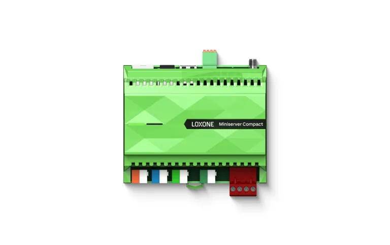
Loxone Miniserver
Loxone Miniserver — Core Controller, Extensions & Capacity
The Loxone Miniserver as the local controller of a building: its role, extension approach, capacity planning, programming and project delivery.
Quick answer
The Loxone Miniserver is the local controller at the centre of a Loxone installation. It executes schedules, logic, interlocks and room control on site, connects to Tree, Air and 1-Wire devices, and exposes interfaces to KNX, BACnet, Modbus and other systems. Extensions add inputs and outputs as the building grows.
What the Miniserver does
The Miniserver is the local brain of a Loxone installation. It stores the configuration, runs the control logic, executes time programmes and scenes, and serves the operator app. It is not only a gateway: the sequences that make a building comfortable and efficient live in the controller, not in a remote data centre. That local-first design means heating, lighting, shading and access keep working when the internet does not. The Miniserver also records the state of the system, provides user access and exposes data to supervisory platforms. That distinction matters during an internet outage, a cloud service change or a decision to move the operator interface to another platform. A controller that depends on the cloud for basic logic is a different risk profile from one that keeps running on site.
- Stores and runs the configuration
- Executes schedules, scenes and logic
- Serves the app and user access
- Keeps working without the cloud
Where it sits in the architecture
The Miniserver sits between field devices and the operator. Below it, Tree, Air and 1-Wire carry devices and sensors; wired inputs and outputs connect plant signals and actuators. Beside it, gateways translate KNX, BACnet, Modbus, DALI and other protocols. Above it, a supervisory or IBMS layer can consolidate several controllers and sites. The controller does not need the upper layer to run the building. That flat arrangement keeps response local and makes the network easier to diagnose than a deep chain of translations. The gateway should be chosen for the data it can expose, not only for the protocol logo on the datasheet. It should also be tested with the real device, because some gateways expose points that do not update reliably under load. Draw the topology before choosing hardware: it exposes where a single cable, switch or gateway becomes a shared risk.
- Field devices on Tree, Air and 1-Wire
- Wired I/O for plant signals
- Gateways for third-party protocols
- Optional supervision above
Extensions and input/output
A Miniserver is rarely asked to do everything on its own. Extensions add inputs and outputs close to the equipment they serve, which shortens cable runs and keeps the panel organised. The choice between wired extensions, Tree devices and Air devices follows the building: new-build projects usually favour wired connections, while retrofit projects use wireless where chasing walls is impractical. Inputs and outputs are not interchangeable with bus devices; each has a role in the point schedule. The design should show which points are hardwired, which are on a bus and which arrive through a gateway. Panel drawings should show terminal numbers, cable schedules and spare capacity, so a later extension does not require reverse engineering. A spare terminal is cheaper than a new panel, but spare capacity should be planned, not discovered.
- Wired extensions for local I/O
- Tree devices on a shared bus
- Air devices for retrofit
- Every point assigned a path
Capacity planning
Capacity is not a single number. It depends on the controller model, the number and type of extensions, the device load on each bus, the logic and graphics the project runs, and the data history it keeps. A room controller with a handful of devices and a plant controller with many physical inputs are different engineering problems. We size the system from the point schedule, add headroom for future fit-out, and segment large buildings by floor, wing or service so that one failure does not stop everything. Final capacity is confirmed against current product documentation for the selected model. A capacity figure quoted without the device list, logic scope and history settings is not a specification; it is a guess. Headroom is not the same as spare parts; both belong in the design. If the point schedule grows, revisit the controller choice rather than forcing the design into a model that no longer fits.
- Start from the point schedule
- Count devices per bus segment
- Allow headroom for future fit-out
- Segment large buildings by area
Programming and operation
Configuration is done in Loxone Config with function blocks, named objects, schedules and logic. The quality of the configuration decides whether the building team can maintain the system after handover. We use consistent naming, document every non-standard function, and keep alarm handling separate from control logic so faults can be traced. The app gives operators room views, scenes and alarms; access rights decide who can change what. Backups are scheduled, and a restore test is part of commissioning rather than an assumption. Naming conventions should be agreed with the building team before configuration starts, because renaming later breaks graphics, trends and alarms. Configuration should also record the design intent: why a delay is set to a value, which machine is lead, and what the fallback is when a sensor fails.
- Function blocks and named objects
- Alarm logic separated from control
- Role-based user access
- Scheduled backup and restore test
Selection and delivery
Selection starts with the building type, the number of rooms, the plant to be controlled and the interfaces required. We produce a point schedule, choose the controller and extensions, design the panel and bus layout, then configure and test. Factory acceptance testing checks the panel and logic before site work; site commissioning checks devices, sequences and interlocks. Handover includes as-built drawings, the point schedule, backups and training. If capacity or scope changes later, the documentation shows where there is room to extend. The selection should be revisited if the point schedule changes materially during design, rather than forced into a controller that no longer fits. A useful check is to walk the point schedule against the panel drawings before the panel is built, not after it is installed.
- Point schedule and controller selection
- Panel and bus layout
- Factory and site testing
- As-built documentation and training
I/O types and signal conditioning
Points reach a controller in different electrical forms. Digital inputs read dry contacts or supervised circuits from pumps, dampers, flow switches and alarms. Analogue inputs read 0–10 V, 4–20 mA or resistance sensors, depending on the module and the sensor. Digital outputs switch relays or triacs for fans, valves and enable signals. Analogue outputs drive 0–10 V actuators and variable-speed drives. Pulse inputs count meter pulses, and calculated points derive values such as running averages, degree-hours or efficiency. Each type needs the right cable, terminal and segregation: mains and extra-low-voltage wiring should not share a duct without appropriate separation, and shielded cable needs a defined earth. Surge protection belongs on exposed plant and long cable runs. Signal conditioning is not optional detail; a 4–20 mA sensor on a 0–10 V input, or a shared reference, produces plausible but wrong readings.
- Digital, analogue, pulse and calculated points
- Correct module for each signal type
- Segregation of mains and extra-low voltage
- Surge protection on exposed runs
Availability, backup and lifecycle
A controller is a single point of failure unless the design accounts for it. Critical plant should fail to a defined safe state when a controller stops, a bus segment is lost or the network disappears. Watchdog behaviour, relay fallback positions and actuator fail positions should be agreed with the mechanical designer, not left to the controls programmer. Configuration backups should be taken at commissioning, after every significant change and before firmware updates; a backup that has never been restored is a hope, not a recovery plan. Critical sites may hold a spare controller and a documented replacement procedure. Firmware and software updates need a test plan, because a gateway or controller update can change point behaviour. Lifecycle planning should identify discontinued devices and the replacement path before spares run out.
- Defined fail-safe states
- Backup after change and before updates
- Spare controller for critical sites
- Firmware test plan and lifecycle path
Miniserver planning factors
17 rows| Aspect | How it is handled | What to confirm |
|---|---|---|
| Control logic | Function blocks, schedules and sequences run locally | Logic complexity and change ownership |
| Room control | Scenes, setpoints and presence per room | Room count and user expectations |
| Third-party interfaces | Gateways for KNX, BACnet, Modbus and DALI | Available protocol and data points |
| I/O expansion | Wired extensions close to the equipment | Signal type, distance and panel space |
| I/O types | Digital, analogue, pulse and relay channels | Voltage, current, isolation and spares |
| Signal conditioning | Correct module, shielding, earthing and surge protection | Sensor type, cable route and reference |
| Tree devices | Shared bus cable for compatible devices | Bus topology and device load |
| Air devices | Wireless connection for retrofit | Signal environment and battery access |
| 1-Wire sensors | Low-speed bus for temperature probes | Sensor run length and quantity |
| Network | Ethernet connection for app and supervision | Addressing, VLAN and remote access policy |
| Power | Dedicated supply and backup where required | Load, earthing and UPS scope |
| Backup and restore | Configuration and data backup schedule | Retention and tested restore procedure |
| Remote access | Optional, authenticated and logged | Who approves access and how it is revoked |
| Enclosure | Panel or cabinet sized for the extensions | Heat, space and future expansion |
| Segmentation | Several controllers by floor, wing or service | Failure boundary and naming consistency |
| Firmware and updates | Test plan before controller or gateway updates | Version compatibility and rollback |
| Spares and lifecycle | Replacement units and end-of-life planning | Criticality, lead time and discontinued models |
Project images
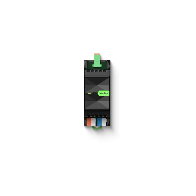
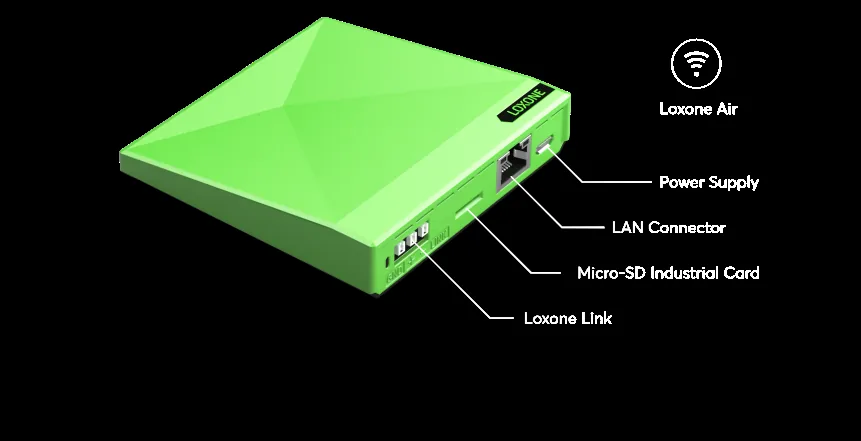
3 images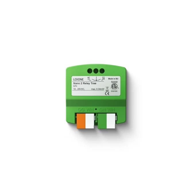
Frequently asked
01What is a Loxone Miniserver?
The Miniserver is the local controller at the centre of a Loxone system. It stores the configuration, runs control logic and schedules, connects field devices and serves the app.
02Is the Miniserver a PLC or a gateway?
It is closer to a controller than a gateway. It runs logic, schedules and room functions locally. Gateways are separate devices used to bring third-party protocols into the system.
03How many inputs and outputs does a Miniserver have?
It depends on the model and the extensions selected. There is no single figure that applies to every project. We size the controller from the point schedule and confirm the final count against current product documentation.
04Can one Miniserver run a whole building?
It can for smaller buildings with a modest device count. Larger buildings are usually segmented by floor, wing or service, with several controllers and a supervisory layer. Segmentation also limits the effect of a single failure.
05Does the Miniserver work without the internet?
Yes. Control logic, schedules and interlocks run locally. Internet connectivity is used for remote access and reporting, not as a condition for normal operation.
06What is a Miniserver Extension?
An extension adds inputs and outputs to the system, usually close to the equipment it serves. It reduces cable length and keeps the panel organised. The required type and number follow the point schedule.
07Can the Miniserver integrate BACnet, Modbus and KNX?
Yes, through the appropriate gateways or interfaces. Each integration needs a confirmed address list, a point map and a test record. Available data depends on the third-party equipment.
08What happens if a Miniserver fails?
The controlled plant may fall back to local safety states, depending on how the actuators and panels are designed. A recent configuration backup allows replacement and restore. Critical sites can hold a spare unit and a documented recovery procedure.
Next step
Bring us the building.
Tell us the building type, systems in scope and the outcome you need. We will map the shortest path to a working system.