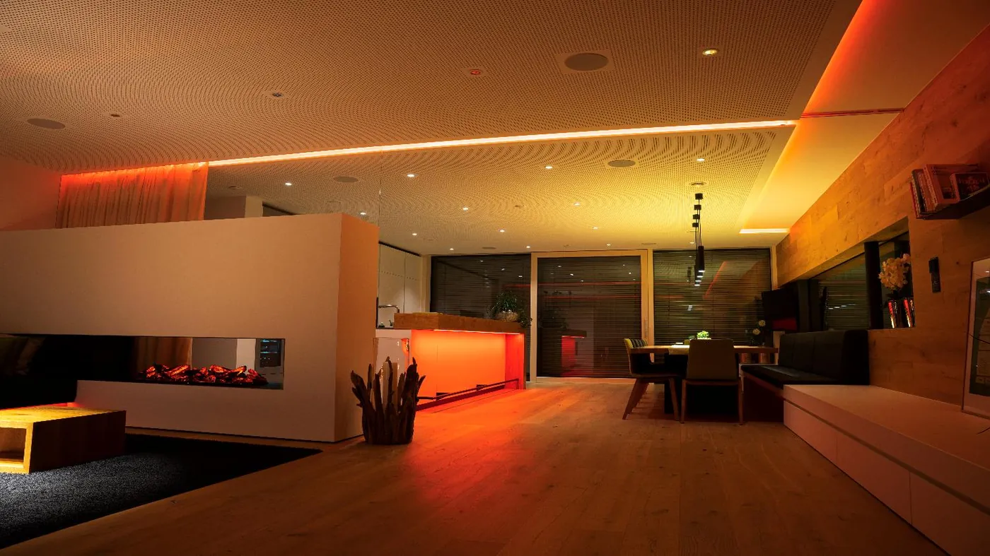
HVAC control
HVAC Control System — Chillers, AHU, FCU & Underfloor Heating
HVAC control system design for chillers, AHUs, fan coils and underfloor heating: control strategies, metering, alarms and commissioning.
What an HVAC control system covers
An HVAC control system sits between the mechanical design and the room. It starts at the chillers, boilers and heat pumps, passes through pumps, valves, air-handling units and ductwork, and ends at fan coils, underfloor loops, radiators and diffusers. Control does not replace mechanical design; it makes the design respond to real conditions. The scope should define which equipment is controlled, which is only monitored, and which safeties remain with the equipment manufacturer. That boundary is as important as the control strategy itself. The control system should also define who owns each sequence, because mechanical contractors, controls contractors and equipment vendors often share the same plant. A clear boundary also prevents controls from being blamed for mechanical faults that were present before the project started.
- Chillers, boilers and heat pumps
- Pumps, valves and distribution
- AHUs, fan coils and ventilation
- Underfloor heating and room terminals
Chillers and heat plant
Plant control is about sequencing, not just switching. Chillers are staged by load, with chilled-water setpoint reset, primary and secondary pump control, isolation valves, cooling-tower fans and run-hour balancing. Boilers and heat pumps need their own staging, return-temperature protection and weather compensation. The sequence should define lead and lag rotation, minimum run times, maximum starts and what happens when a machine faults. Safety limits remain with the equipment; the control system coordinates the plant around them and records the evidence for review. Trend data from the plant is more useful than a single snapshot: it shows whether staging follows load and whether a machine is short-cycling. The same trend shows whether the lead machine is being rotated or quietly carrying the building. Condenser-water control deserves equal attention, because tower fans and bypass valves decide how efficiently the chiller can reject heat.
- Lead and lag rotation
- Chilled-water setpoint reset
- Pump and valve sequencing
- Fault handling and run-hour balance
Air-handling units
An AHU control sequence holds supply-air temperature or room conditions by modulating chilled-water and heating valves, dampers and fan speed. It also protects the unit: filter pressure, frost risk, smoke input and fan proof. Demand-controlled ventilation uses CO2 or occupancy to move fresh-air dampers rather than running at a fixed minimum. Economiser or free-cooling logic uses outdoor air when conditions allow. Each mode needs a clear transition, so the unit does not hunt between heating and cooling. The sequence should be written, tested and handed over with the unit. A written sequence of operation is the reference for testing, training and later changes; without it, the building depends on the original programmer. It should be updated when the strategy changes, not left as a commissioning artefact. VAV systems add terminal airflow control, reheat and pressure reset, which must be coordinated with the AHU rather than tuned in isolation.
- Supply-air temperature control
- Valve, damper and fan modulation
- Demand-controlled ventilation
- Filter, frost and smoke protection
Fan coils and room control
Fan coil control is where occupants feel the system. A room controller reads temperature and sometimes humidity, CO2 or window status, then drives a valve and one or more fan speeds. Two-pipe and four-pipe systems need different changeover logic, and cooling and heating setpoints need a deadband to prevent fighting. Occupancy and window contacts can drop the room to an energy-safe mode. Setpoint limits stop local overrides from defeating the plant strategy. In hotels, the same room logic follows check-in, check-out and guest presence. The room controller should fail to a safe position, and the valve should be selected so that a lost signal does not leave the coil in an unsafe state. Guest-room logic should hand back to the local occupant without requiring a call to the front desk. A room that is comfortable but impossible to override is as much a failure as one that is never controlled.
- Room temperature and humidity sensing
- Two-pipe and four-pipe changeover
- Occupancy and window contacts
- Setpoint limits and guest modes
Underfloor heating
Underfloor heating responds slowly because the slab stores heat. Control therefore works on water temperature and anticipation, not rapid room setpoint changes. A mixing valve or manifold actuator holds the supply-water temperature, often with weather compensation. Room thermostats open and close loops or zone valves, and a floor-temperature limit protects the screed and the finish. In cooling mode, dew-point protection is essential before cold water enters the slab. Zoning should follow how the space is used; too many small zones can make the plant cycle unnecessarily. Because the slab responds slowly, a schedule change should be planned ahead, not used as a quick fix for a cold morning. Weather compensation should be tuned to the building, not copied from a template. Manifold actuators also need a defined position on power loss, and the hydraulic design must provide the flow that the control strategy assumes.
- Slab temperature and anticipation
- Mixing valve and weather compensation
- Floor-temperature limits
- Dew-point protection in cooling
Strategies, metering and commissioning
Good HVAC control is a set of simple strategies applied consistently: schedules that follow occupancy, deadbands that prevent hunting, PID or PWM loops tuned to the equipment, weather compensation, demand limiting and fault detection. Metering makes the result visible: thermal energy, electricity, run hours and valve position. Alarms should distinguish a genuine comfort excursion from a sensor fault. Commissioning tests each point, strokes valves, checks sensor calibration and proves every sequence and interlock. Seasonal commissioning then confirms the strategy in heating and cooling conditions. Metering should be installed where it answers a question: plant efficiency, tenant allocation, or the effect of a control change. Commissioning records should include the as-found and as-left values, so later drift can be distinguished from design intent. A trend that is never reviewed is only storage; the operating routine should include a periodic look at plant behaviour and alarm frequency.
- Occupancy schedules and deadbands
- PID and PWM loop tuning
- Thermal and electrical metering
- Point testing and seasonal commissioning
Sensors, loops and tuning
Control quality starts with sensors and valves, not with the tuning screen. A room temperature sensor should be placed where it sees the occupied zone, away from sunlight, diffusers and external walls. Duct sensors need representative locations and enough insertion depth; averaging sensors help across wide ducts. As an industry planning reference, good room temperature measurement is often specified in the order of ±0.5 K, humidity in the order of ±3–5% RH, and CO2 in the order of ±50 ppm plus a percentage of reading, but the project specification should state the actual requirement. Control loops are usually PID for modulating valves and dampers, and PWM or time-proportional for thermal actuators and fan stages. Deadbands prevent hunting, anti-windup prevents integral saturation, and valve authority decides whether a loop can control at part load. Tuning should be done at part load as well as design load, because a loop that is stable at full flow can oscillate at 20%.
- Sensor placement and representative readings
- Accuracy stated by the project specification
- PID, PWM and deadband settings
- Tuning at part load as well as design load
Commissioning tests and common failure modes
Commissioning begins before the control system is energised: check panel construction, wiring, terminal numbers and sensor installation against the drawings. Then verify every point, stroke every valve and damper, compare sensor readings with a reference, and prove each sequence in every mode. Interlock tests follow, including fire mode, frost protection, pump proving and changeover. Failure tests confirm what happens when a sensor is disconnected, a bus segment is lost or a controller restarts. Seasonal commissioning repeats key tests in heating and cooling conditions. As an industry planning reference, a small project may need a few weeks of commissioning and a large plant several months, but the real driver is point count, trade readiness and access. Common failures are familiar: sensors in dead air, valves leaking or oversized, simultaneous heating and cooling, short cycling, sensors drifting, overrides left on and schedules never adjusted after handover.
- Pre-functional and point-to-point checks
- Stroke, calibration and sequence tests
- Failure-mode and seasonal tests
- Overrides, schedules and drift reviewed
HVAC control scope by equipment
18 rows| Equipment | Control objective | Typical inputs | Typical outputs |
|---|---|---|---|
| Chiller plant | Stage machines to load and protect minimum run times | Supply and return water temperature, flow, load | Start/stop, setpoint, valve and pump commands |
| Cooling towers | Maintain condenser water temperature and cell balance | Condenser supply and return, outdoor condition | Fan speed, cell staging, bypass |
| Primary and secondary pumps | Match flow to demand and protect differential pressure | Differential pressure, flow, status | Variable-speed drive, lead/lag, isolation valve |
| Boilers and heat pumps | Stage heat sources and protect return temperature | Flow and return temperature, outdoor condition | Start/stop, setpoint, mixing valve |
| Air-handling units | Hold supply-air or room conditions and protect the coil | Temperature, humidity, CO2, filter pressure, fan status | Valve and damper position, fan speed, enable |
| Heat recovery | Recover heat without risking frost or cross-contamination | Exhaust and outdoor temperature, pressure | Damper position, bypass, wheel or plate control |
| VAV terminals | Hold zone airflow and temperature with minimum fresh air | Airflow, room temperature, damper position | Damper, reheat valve, airflow setpoint |
| Fan coil units | Hold room setpoint with quiet, stable operation | Room temperature, occupancy, window contact | Valve position, fan speed, mode |
| Underfloor heating | Control slab temperature without overshoot | Room and supply-water temperature, dew point | Mixing valve, zone valve, pump |
| Radiators and perimeter heating | Hold room temperature without local overheating | Room temperature, window contact, supply water | Valve or actuator, pump enable |
| Chilled beams and radiant panels | Control water temperature and prevent condensation | Room temperature, humidity, dew point, water temperature | Valve, changeover, condensate alarm |
| Dedicated outdoor air systems | Condition fresh air independently of room terminals | Temperature, humidity, CO2, filter pressure | Valves, fans, dampers, energy recovery |
| Kitchen extract and make-up air | Maintain pressure and remove grease-laden air safely | Pressure switch, fan status, duct temperature | Fan enable, damper, variable-speed drive |
| Ventilation and exhaust | Match fresh and extract air to occupancy | CO2, occupancy, pressure, fan status | Damper position, fan speed, enable |
| Humidification | Hold humidity without condensation risk | Relative humidity, temperature, duct condition | Valve, steam or electrode control |
| Thermal metering | Measure delivered heating and cooling | Flow, supply and return temperature | Energy totals, trend records, alarms |
| Electrical metering | Attribute plant consumption to equipment | Current, voltage, power, energy | Consumption trends, baselines, reports |
| Plant-room environment | Protect equipment from heat, humidity and water | Room temperature, humidity, leak detection | Fans, alarms, maintenance ticket |
Project images
3 images

Frequently asked
01What is an HVAC control system?
An HVAC control system monitors and regulates heating, cooling, ventilation and humidity. It sequences plant, modulates valves, dampers and fans, holds setpoints and reports alarms and energy data.
02Can one system control chillers and fan coils?
Yes. Plant and room control usually run in the same system, with different sequences and time constants. The chiller plant is controlled at equipment level; fan coils at room level. Metering and alarms bring both into one view.
03What is the difference between an AHU and an FCU?
An AHU conditions and distributes air for a larger area, often with ducts, coils, filters and fans. An FCU serves a single room or zone, usually with a coil and a small fan. Their control sequences and point counts differ.
04How is underfloor heating controlled?
Usually through a mixing valve or manifold actuators that hold supply-water temperature, with room thermostats opening zone valves. Weather compensation and floor-temperature limits protect comfort and the floor construction.
05What is weather compensation?
Weather compensation adjusts supply-water temperature according to outdoor temperature. Colder weather raises the supply temperature; milder weather lowers it. The result is steadier comfort and less unnecessary energy use at part load.
06Which protocols are used in HVAC control?
BACnet/IP is common for chillers, AHUs and packaged plant; Modbus for meters, inverters and some controllers; 0–10 V and dry contacts for simpler equipment. KNX may appear in room control and fan coils.
07How is HVAC control commissioned?
Commissioning checks every point against the schedule, strokes valves, verifies sensor readings, proves each sequence and interlock, and records the results. Seasonal testing then confirms heating and cooling performance under real load.
08Can HVAC control reduce energy use?
It can, by matching plant operation to demand, avoiding simultaneous heating and cooling, correcting schedules and exposing faults. The size of the effect depends on the building, the equipment and how well the sequences are commissioned and maintained.
Next step
Bring us the building.
Tell us the building type, systems in scope and the outcome you need. We will map the shortest path to a working system.